I found the UAI-CCD website many years ago:
On the left panel of the page is a flag for Italian & English but only an introductory page exists in English.
I downloaded all the webpages and had “google translate” them into English. This worked except for a few words that could be inferred from the context. Some translation errors: Sockets – clogs, Voltage – tension, you get the idea.
I ordered the CCD chip from FRAMOS in Europe. They quoted me a shipping charge of over $100.00 so I asked them to mail it (no tracking, no insurance) – cost was reasonable and it arrived just fine in a few weeks.
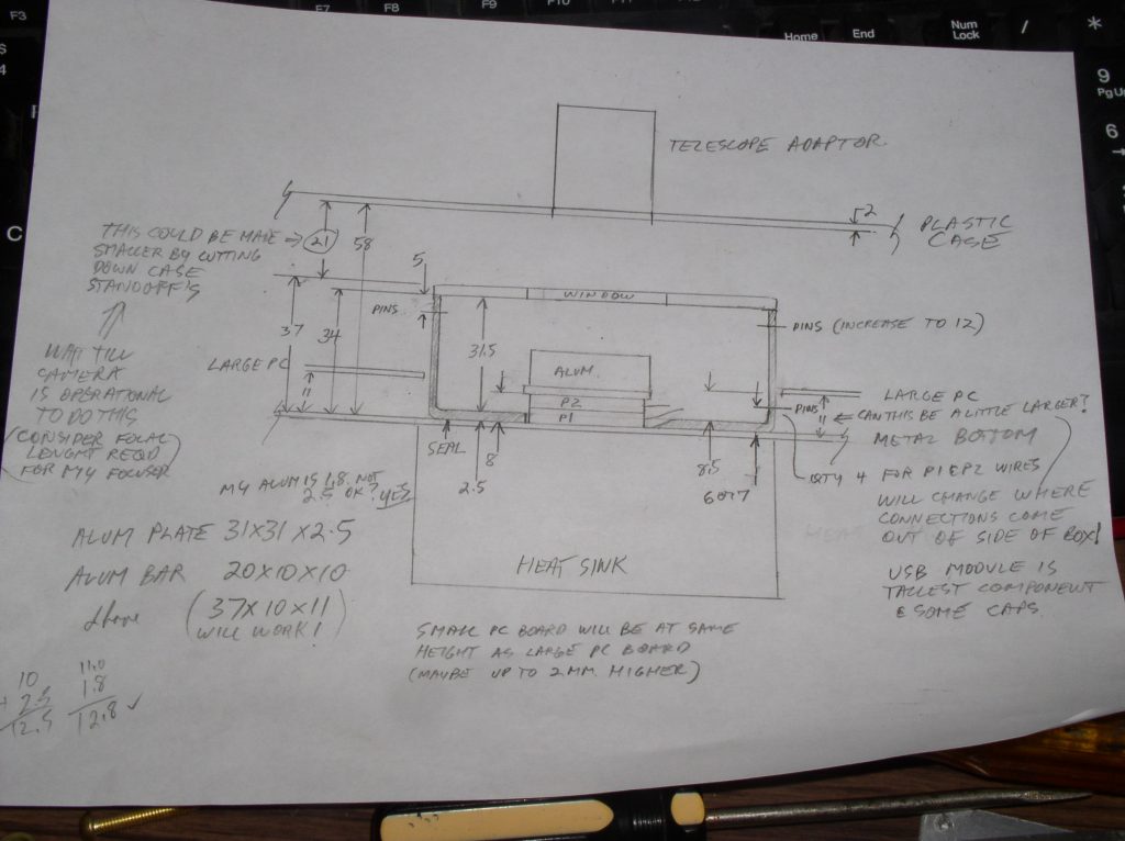
Most of the parts were able to be sourced from US suppliers. The only thing I could not find was the “cold box”. It had metric measurements that had to be very precise. Today I would design it in OpenScad and 3d print it. At the time I did not have my 3d printer so I made it from foam and fiberglass – which should be insulated better than the specified box.
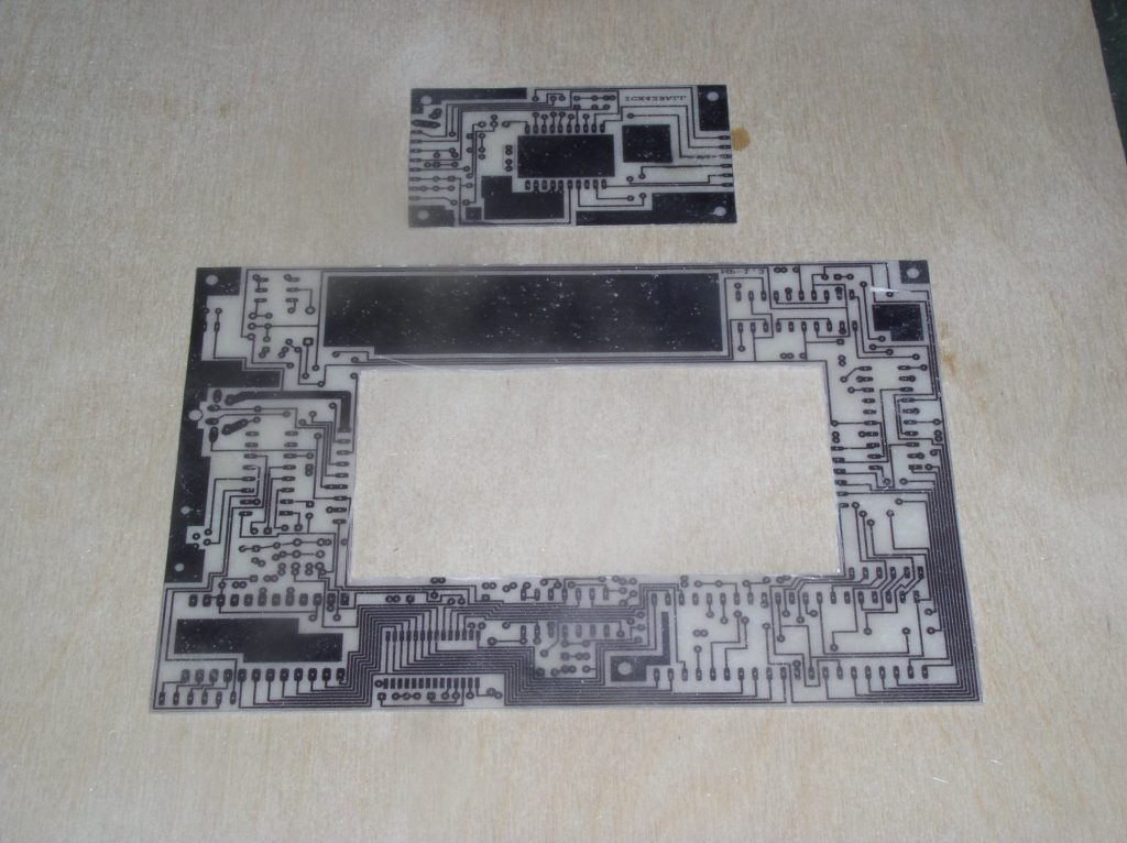
The software to open the printed circuit boards is FIDO cad. You guessed it – it’s in Italian (free software). Luckily the website provides enough pictures of the program to enable printing of the files without learning any Italian.
I wired the peltier cooler directly from the power supply – a very high current device and I saw no need to run it through a trace on the camera chip board.

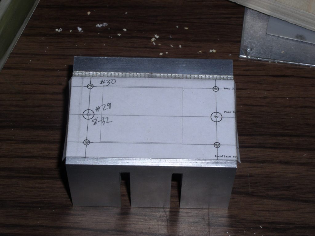
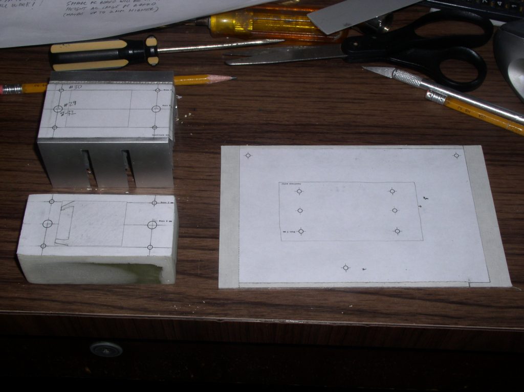
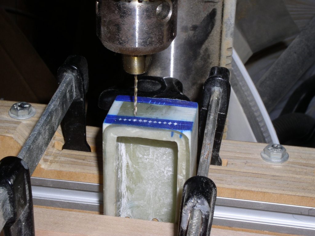
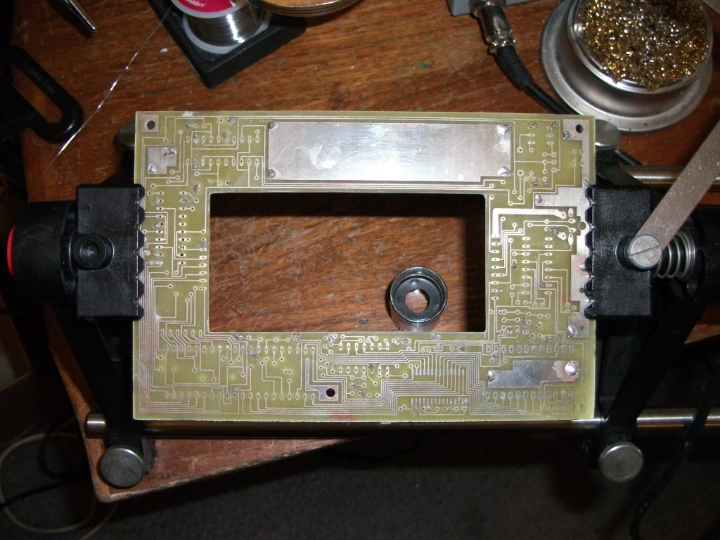
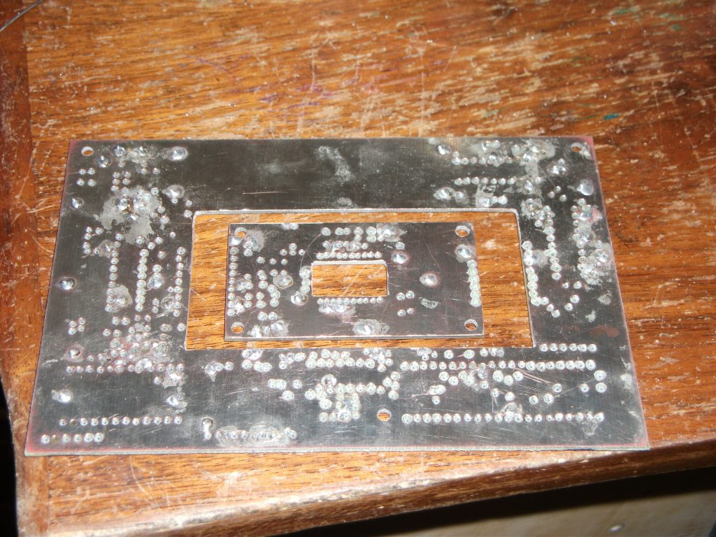
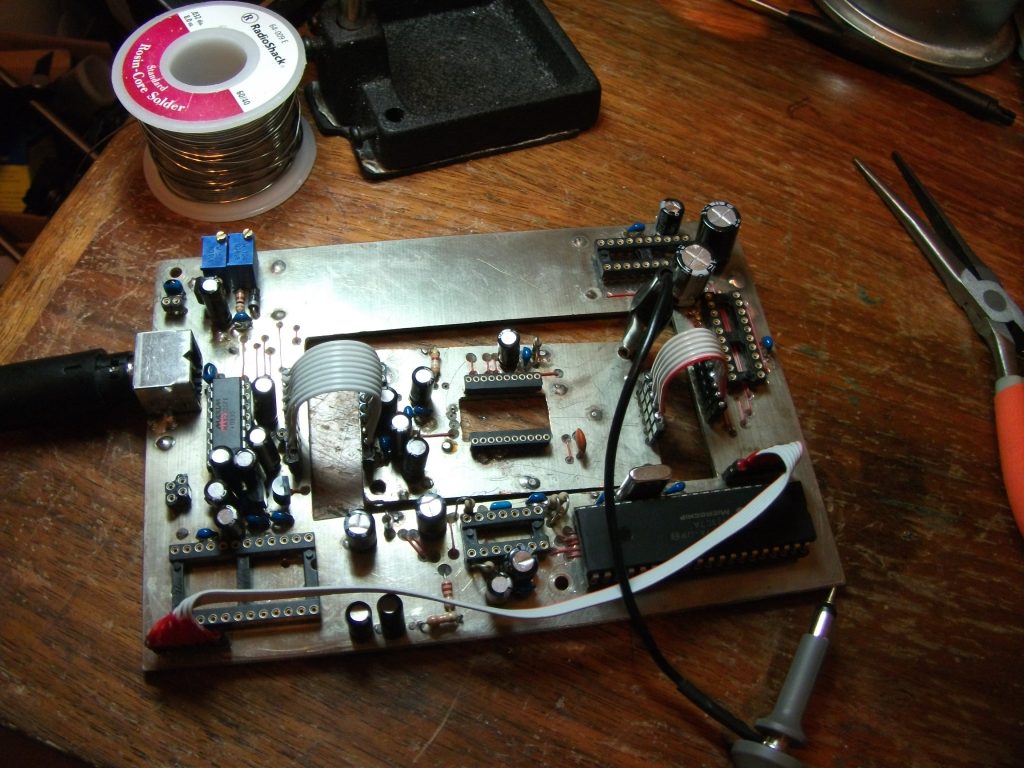
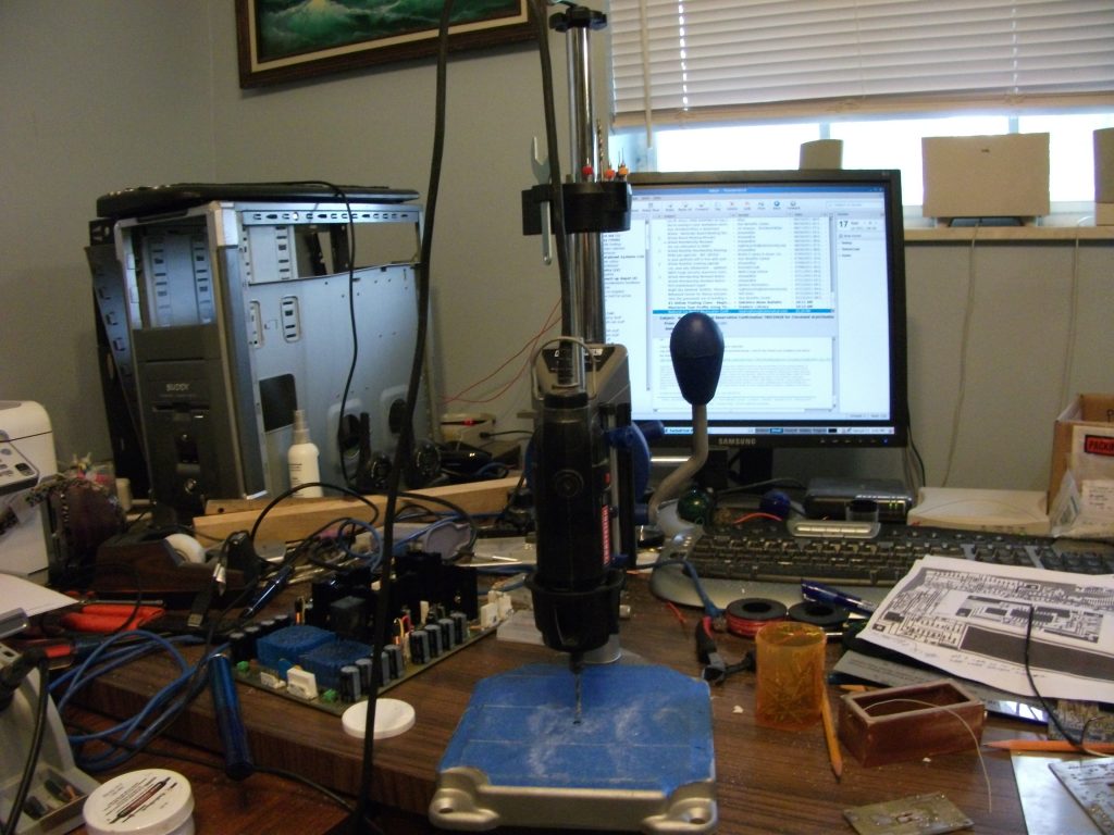
drill template more drill templates clocks working drilling pas through holes the main board chip board, main board completed boards test print of pc boards ps on left, cold box right assembly sketch
So far the camera “sees” shades of light and dark. I won’t be able to focus an image on it until I complete the assembly. I still need to make a glass cover plate for the cold box and create a controller for the peltier chip.
I had originally built a (very physically large) power suuply for the camera. The ps was larger than the camera! It was a +/- 15V dual stage built up from components. I felt this was the best way to get an extremely low ripple noise power supply. You can see it in one of the pictures above. I have since figured out that I can achieve the same or better level of ripple using 2 single chip voltage controllers in series for each voltage. The design is done – it’s on my list of things to make.
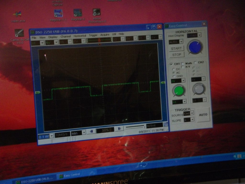
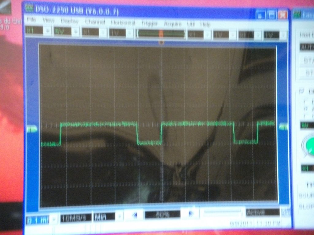
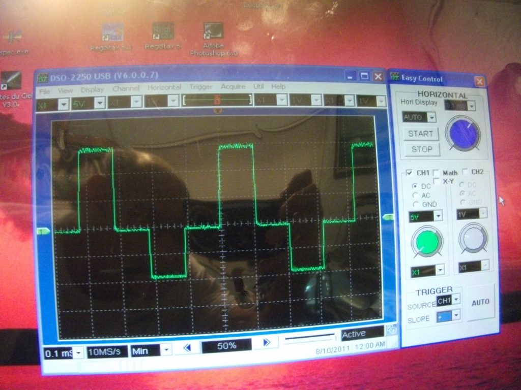
My scope is the DSO-2250 USB. Works great.
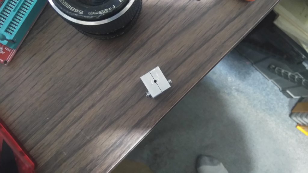
Update November, 2021: The camera is finally finished! The date on the first pcb I made for this project says 1/23/2009. Only 13 years to complete (so there is hope for all of you with unfinished projects yet). I tested the ability of the camera to capture an image by placing a small aluminum block with a tiny hole in the center directly on the ccd (with the protective plastic still on) and took a one second exposure and got the “image” of the hole in the block. It works!
I ended up redesigning some stuff. I discarded the fiberglass box “cold chamber” and 3d printed one. Much nicer looking with more space in the box. I used a piece of glass that was slightly larger than needed for the cover glass to the cold box and made it fit by changing the cover of the cold box. I redid the connections to the ccd pcb with solid wires that fit the female pin headers on the pcb’s. I totally redesigned the power supply. For the camera power I used a small power supply module that provides + and – 15V. Nothing like this was available off the shelf when I started the project. For the peltier cooler I designed a power supply from components to control the temperature to a setpoint and also limit the current to the peltier to 2.5A. I have achieved temperatures as low as 42 deg F at the cold finger near the chip. The ccd “cold chamber” has not been sealed yet and I have not added a dessicant pack yet so I get condensation on my cover glass below about 55 degrees. Also if I get the chip too cold the software hangs while trying to calibrate the chip.
The acquisition software that the designers created was designed for Windows XP. My laptop is a Windows 10 machine. So while the software works it is a bit “fussy” i.e. if you specify the wrong comm port to connect to it crashes and needs to be restarted instead of gracefully giving you an error message. Exposure times are in a combo box and are predefined. I will take a series of exposures and increment the file names. There is no Ascom or equivalent driver that I can find so the camera will not work with other acquisition software (I started writing an Ascom driver for the camera and quickly discovered that even with the new templates that come with Ascom it is currently beyond my skill level). It has a focus mode that works well.
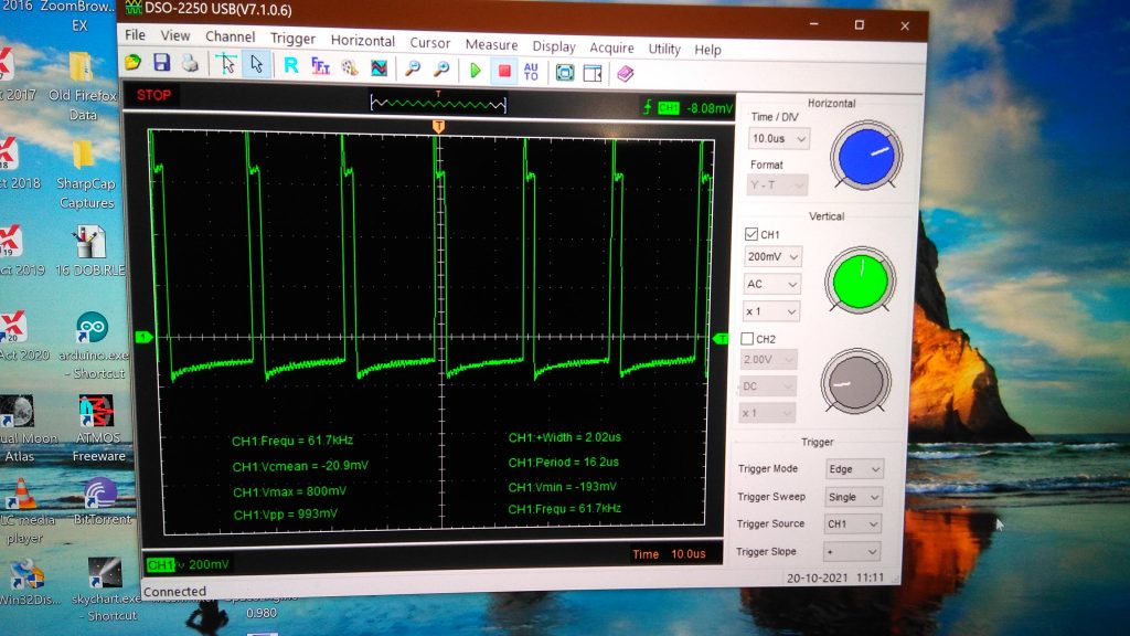
This is the waveform of the output of the ccd chip. The very peak value is the reset. The small horizontal section above zero is the precharge. The line below zero represents the pixel value. The darker it is the closer to zero the pixel line gets.
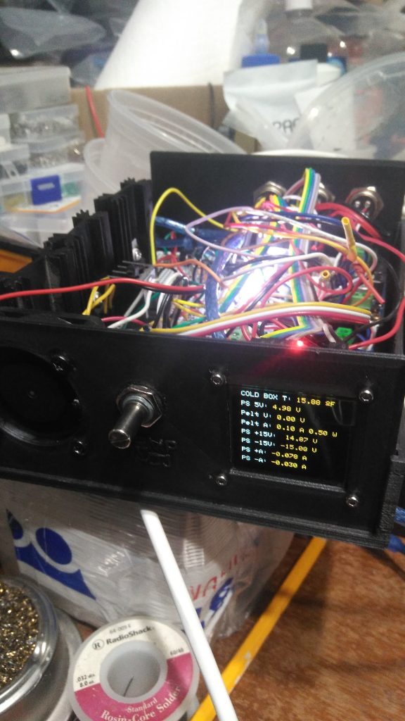
This is the new power supply for the camera. The shaft in the center is the temp. setpoint for the the peltier cooler. The display reads the voltages and currents to the camera. To the left is a fan. There is an arduino nano in the box to control the display. The peltier proportional control with current limiter is made up from individual components. The camera supply is a small module located just behind the fan. The camera uses too little current for the current sensors to work on the + and – 15V supply but the one for the peltier works fine.
The above is a schematic of the power supply
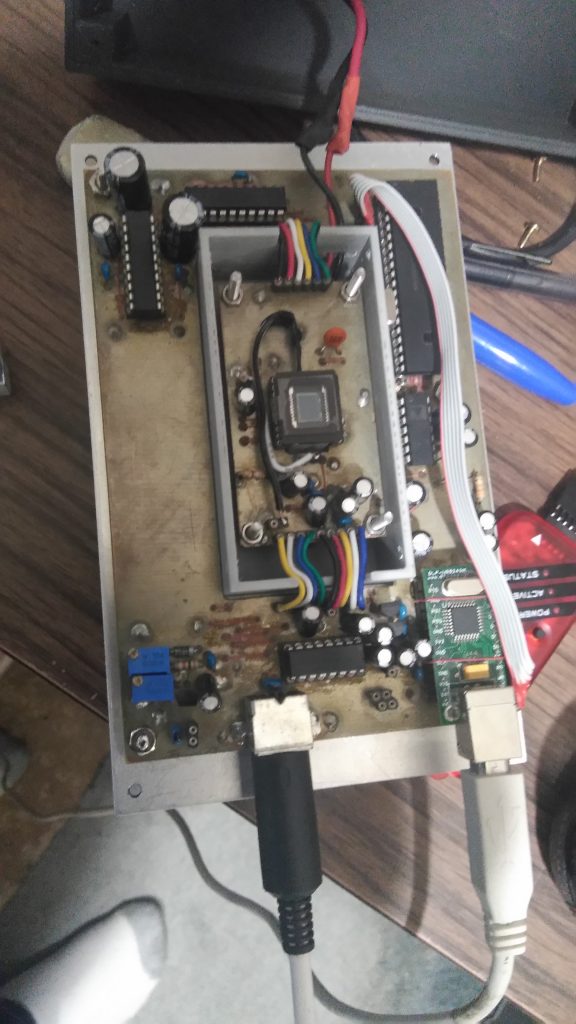
This is the completed camera.
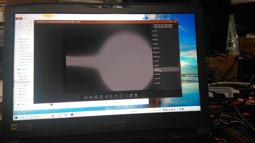
This is the first image taken by the camera. The small aluminum block below was placed directly on the ccd sensor. The line is light reflecting down the groove where the blocks meet. Exposure time was one sec.
Need to put it in a telescope and get some images!