The motor on my G4003G burned up after about a year and a half. After hearing the price of a new motor from Grizzly (over $500.00) and seeing posts from others that the original motor burnout rate is more prevalent than it should be – I decided to convert to a 3 phase motor with a VFD. More than one owner claimed that this is a “drop in” conversion – Not!. I had problems finding detailed information about how to do it. Here is what I did:
There are the major parts I ordered (pricing was 3/2017) :
| Part | Model # | MFG | Supplier | Cost |
| VFD | WJ-200-015 SF | Hitachi | Precision Electric | $281.30 |
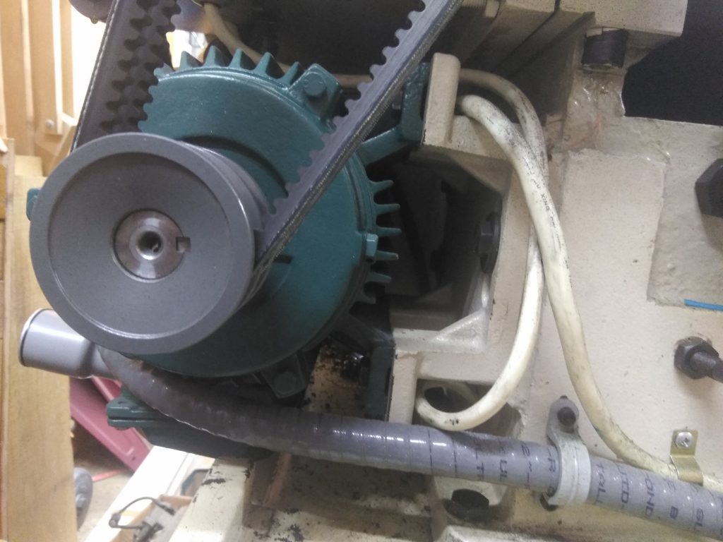
| Motor | 2 HP 1800 rpm | Leeson | Surplus Center | $314.60 |
| Pully | 2.55 OD 7/8 Bore | Surplus Center | $10.00 | |
| Cabinet | NBB-10265 | BUD | Amazon | $82.00 |
| Fan | Axial 1225 | AC Infinity | Amazon | $18.99 |
| Legend Plate | ECX2640 | Automation Direct | $3.50 | |
| Pot | ECX2300-5K | Automation Direct | $36.50 | |
| Locking Recptical | NEMA L15-30R | Amazon | $9.95 | |
| Locking Plug | 2721 30A | Leviton | Amazon | $15.45 |
| Fan Filter | FF121 | Amazon | $4.99 | |
| Total | $777.28 |
Mistakes I made:
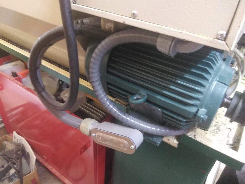
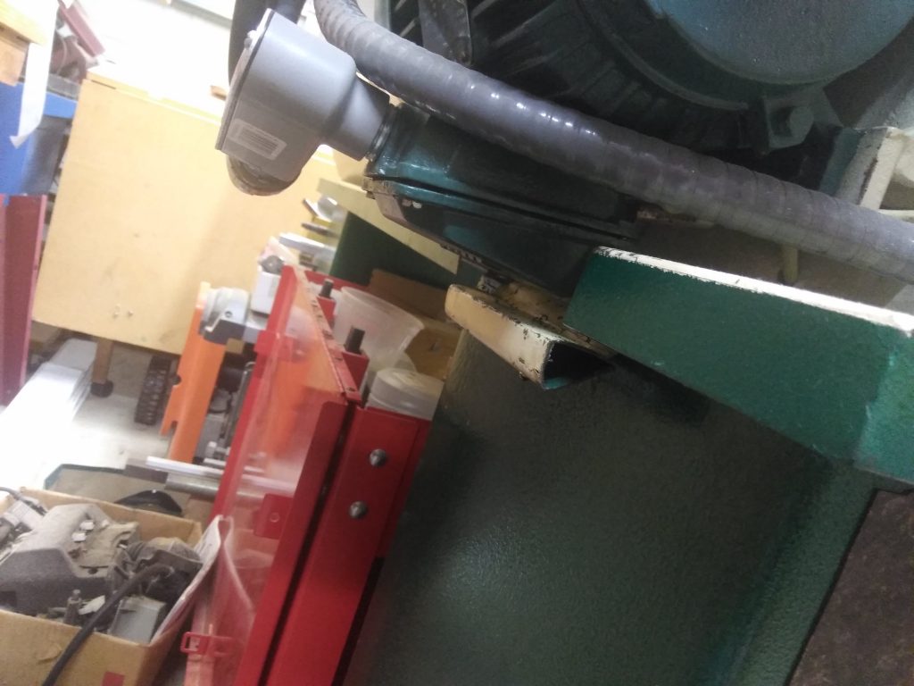
- I ordered the motor with the head on the side of the motor (this is what was in stock). This resulted int the motor head pointing down when the motor was installed on the lathe. This created 2 problems:
- I needed to cut the lip of the drip pan to make clearance for the motor. Could be a serious issue if you use flood cooling (I have no plans for this).
- The head needed to be terminated before the motor was installed on the lathe.
- Solution order a motor with the head on the top of the motor.
- I did not seal the control panel lamination and now it is soaked with oil – still legible.
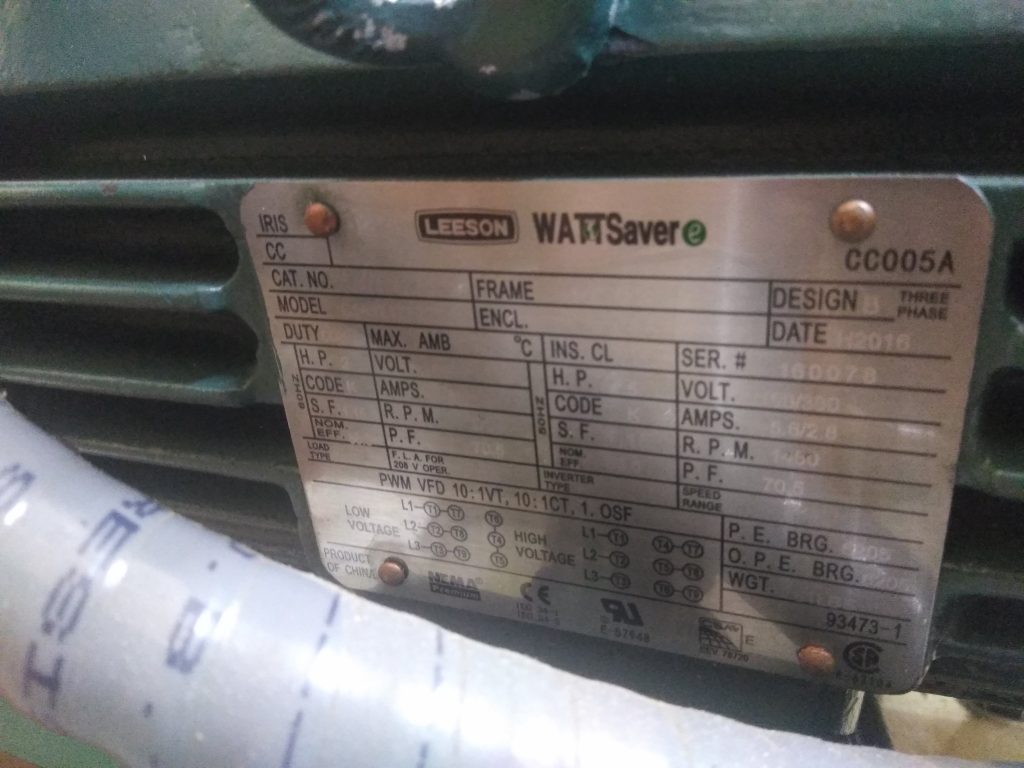
Motor Specifications:
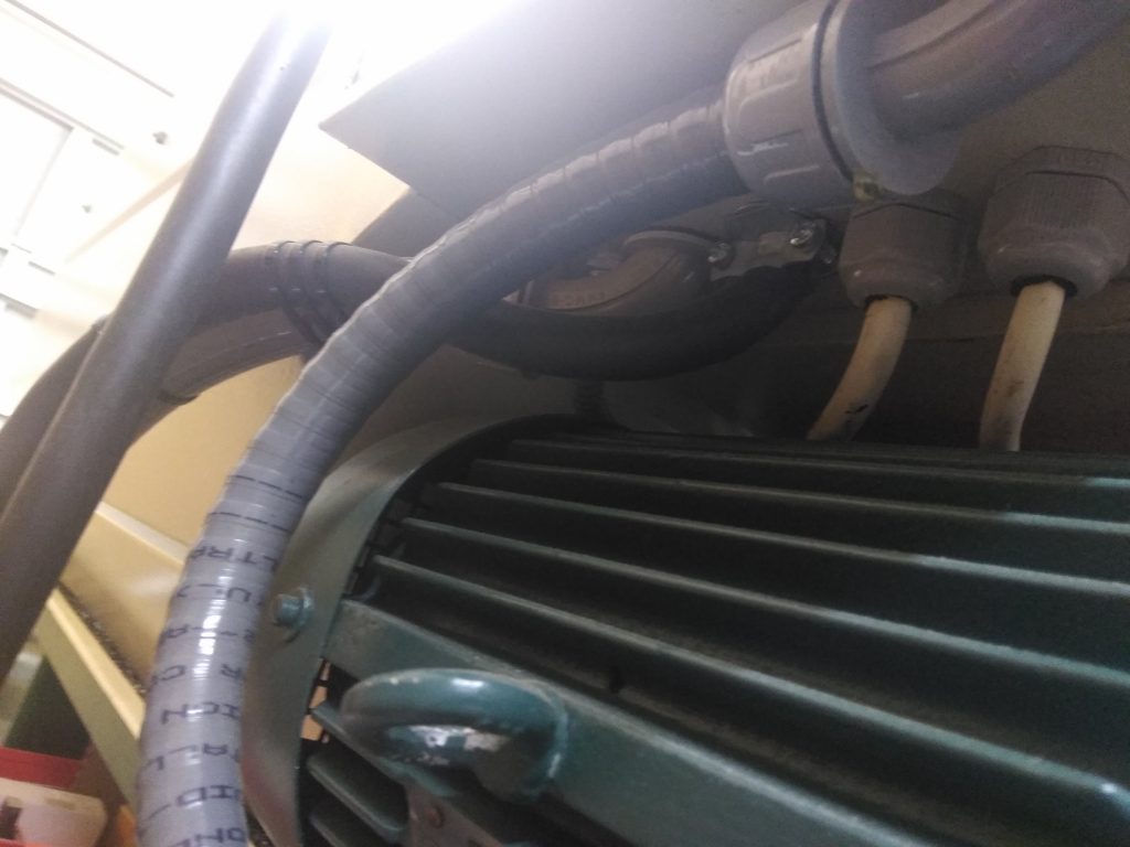
Leeson Wattsaver TEFC (totally enclosed fan cooled), 2HP, 1800 RPM, 230/460V, 3 phase, inverter rated, 7/8″ shaft, 145T frame (bolts up to G4003G without any modifications, 1.15 service factor (important), overload protection included (also important – these are the 2 red wires in the motor head), 6A full load at 230V .
Inverter Specifications:
Hitachi WJ2000-015SF, 2HP, single phase, frequency inverter. This drive accepts a (208-240V) 220V single phase input and provides a 240V 3 phase output to drive the motor. Output current is up to 8 amps (motor only requires 7A at the 1.15 service factor). Requires an external pot.
Here are the wiring diagrams I used to wire everything:
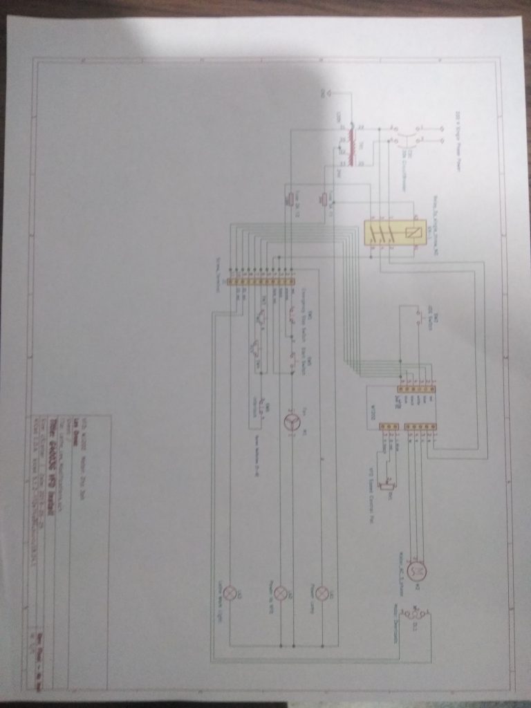
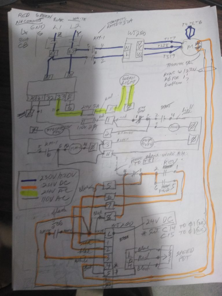
I feel the above sketch is easier to understand than the schematic. The various voltages are color coded. KM-1 is the only contactor retained in the electrical panel. In the control panel I retained the Jog switch (just because it was there). In hindsight I would remove this as I never use it.
The power was originally hardwired into the electrical panel directly from my circuit breaker panel. As part of this upgrade I added an outlet in the ceiling above the lathe with a locking plug.
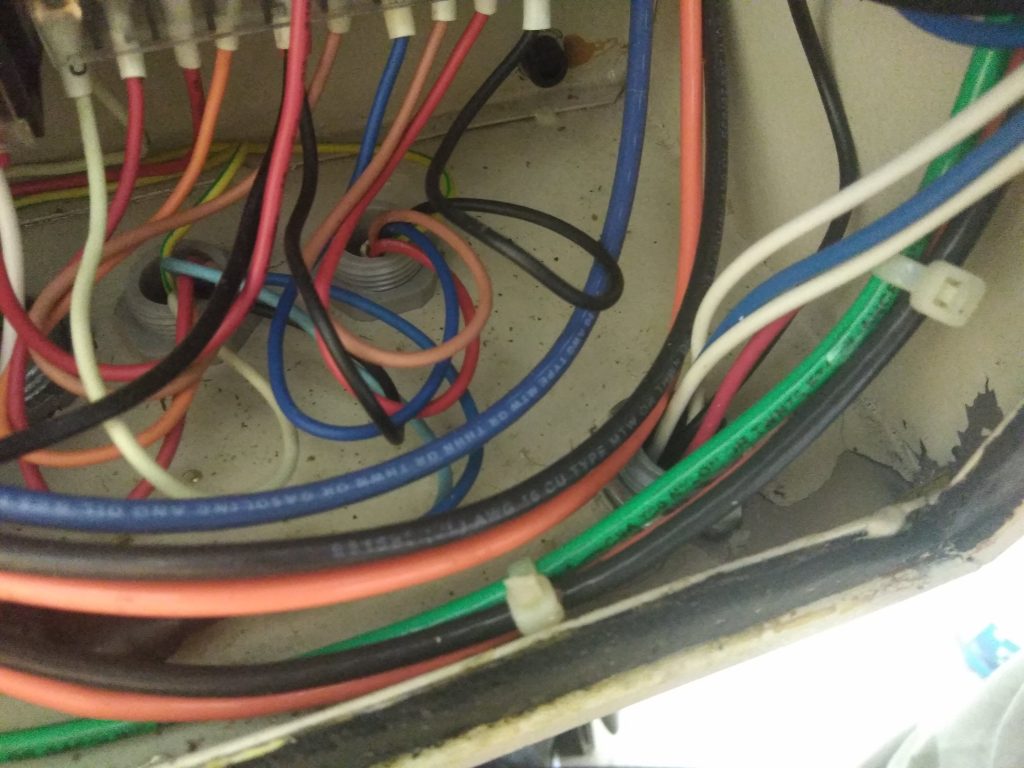
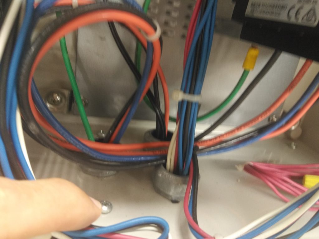
I added liquid tight flex to get the additional wires to the control panel from the electrical box.
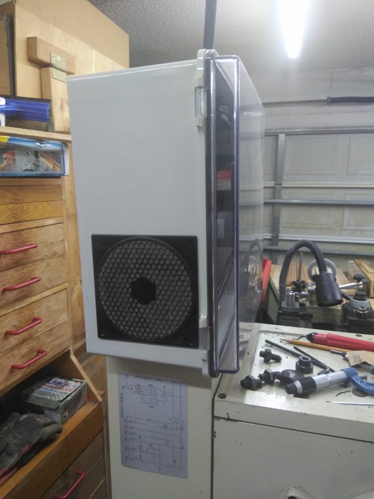
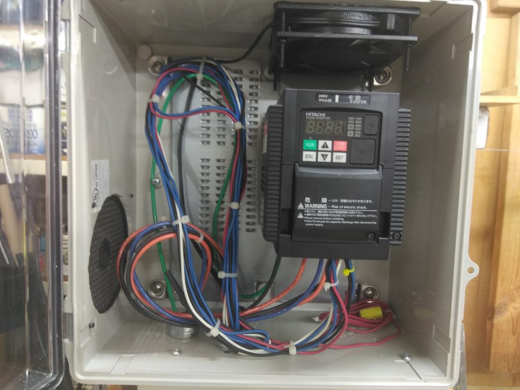
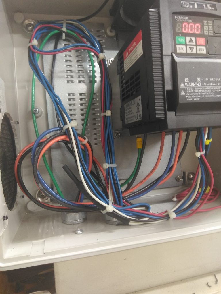
The plastic box I ordered for the VFD worked out perfectly. Just the right size for the VFD and wiring. Notice the “service loops” on the wiring. This allows for changes. The fan in the box comes on with the VFD. Tip: before drilling the holes in the top of the panel tape a piece of plastic sheet inside the panel back near the top and let it drape out the bottom of the panel. The swarf from the drilling then ends up on the floor instead of the bottom of the panel (thanks to whoever posted a picture of this – I don’t remember where I got this idea.
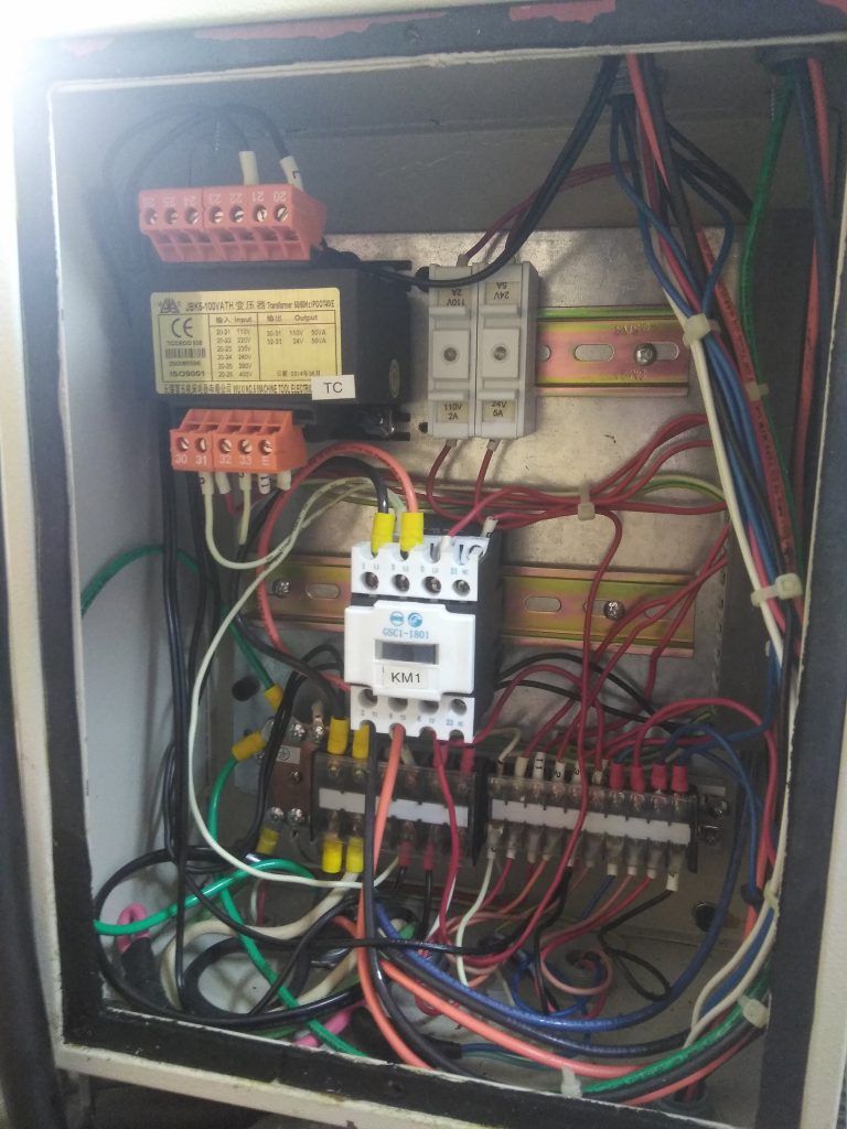
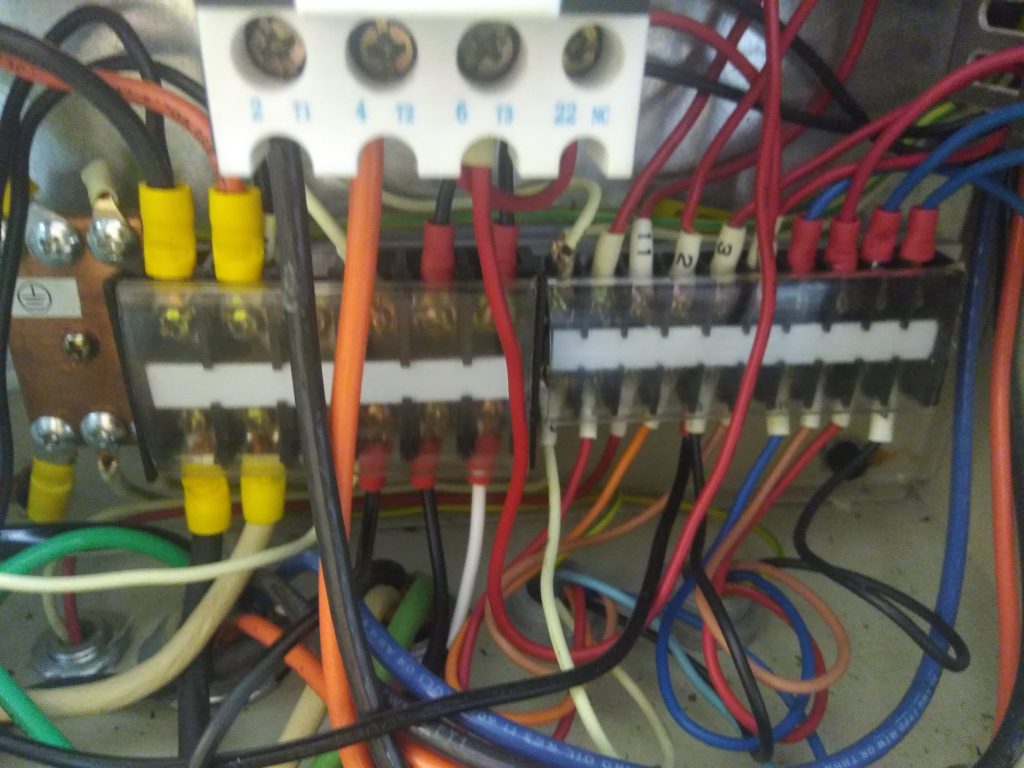
The terrifying part of this conversion was stripping out the unneeded contactors from the electrical panel and installing the new wiring (will this really ever work again?……..). Note that the motor connections T4, T5 & T6 get wire-nutted together in the motor head. I forgot this in the schematic – but it is shown in the sketch.
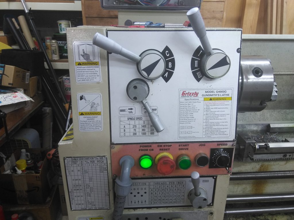
The panel lettering was done in Libre OfficeWriter and printed on plain paper and laminated. The edges of the lamination were not sealed and oil has now thoroughly soaked the paper under the lamination. The legends are still very legible.
The VFD has literally hundreds of settings and options only a few need to be set.
VFD Configuration – this is what works for me:
Note: do not apply power to motor until H004 and A082 are programmed.
| A001 | Frequency Source | 01 Control Terminal |
| A002 | Run Command Source | 01 Control Terminal |
| A038 | Jog Stop Mode | 00 Free-run stop |
| A044 | V/f characteristic curve | 03 Sensorless vector (SLV) |
| A062 | Frequency lower limit | 7 Hz |
| A082 | AVR Voltage Select | 230 V |
| B012 | Level of electronic thermal | 6 (this is in amps – not%) must match motor |
| C003 | Input 3 | 06 Jog |
| H004 | Motor Poles Setting | 4 poles (=1800 rpm) must match motor |
| F001 | output frequency setting | should vary from 7Hz (A062) to 60 Hz as you turn the pot from min. to max. |
| F002 | Acceleration time | 3 sec. your preference |
| F003 | Deceleration time | 2 sec – this may need to be longer when you use higher gear rpm settings – if you get trips – increase this |
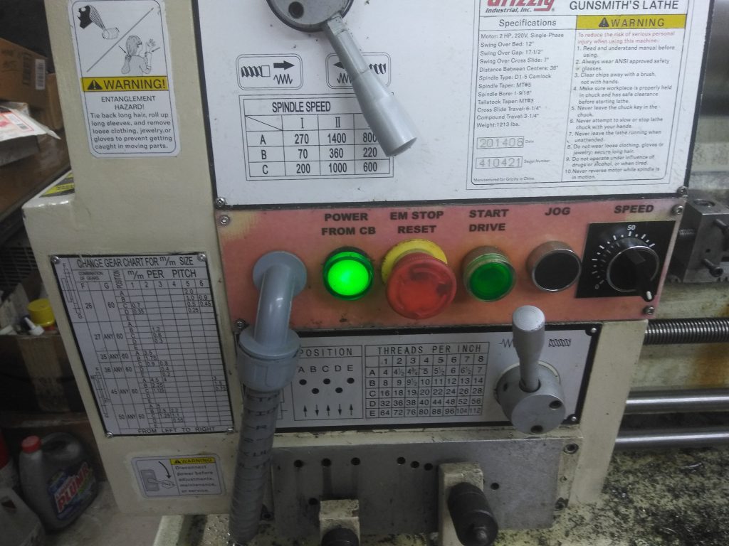
Results: Simply Amazing!
- The lathe runs smoothly from about 70 rpm to 600 rpm in the 600 rpm setting.
- I hardly ever have to change from this setting. I will change to a faster gear if I am turning brass or aluminum, etc.
- I’m not sure why but the finish on all materials has improved.
- At the 600 rpm setting (only) the VFD display reads RPM/10 so once you find the speed that provides the finish you want it is easy to dial it back in.
- I routinely part off mild steel at 270 rpm using the rear toolpost.
- Motor runs really cool. Just slightly warm to the touch (the stock motor used to run hot – don’t know why).