Background:
Most of my machining work is one off parts: making tools for the shop, making telescope parts, etc. I will not be doing production runs except for the occasional time I need a few multiple copies. So here are my reasons for CNC: not having to manually crank the Z axis long distances – that gets old really fast. Rapid moving of the table to the left to mount the rotary table and then back to center. Using the rotary table to precisely place holes on a circle (both vertically and horizontally) and the occasional complex part where writing a few lines of code insures precise milling. Being able to mill arcs and circles. Engraving. I will post some of my simple Gcode files for my projects. I purchased a hand held control to make it easy to use the mill without having to write Gcode.
I decided not to replace the lead screws with the ball style as many have done. I found Daniel E. Kemp’s site “hossmachine” (his site does not appear to be working now) and purchased his CD. There were no plans specifically for the PM30-MV mill but I was able to take his drawings for the grizzly mill and modify them to mount the stepper motors on my mill. This is basically his “Phase I” solution to CNC a mill. Also I do not control the spindle from Mach III. I still use the start/stop and speed controls on the mill control panel.
The only downside to the conversion is that if i just want to drill a hole or any quick operation I still need to boot the computer to use the handheld controller. This is not a deal breaker as it only takes about 30 seconds to boot XP with the solid state drive.
The computer and software:
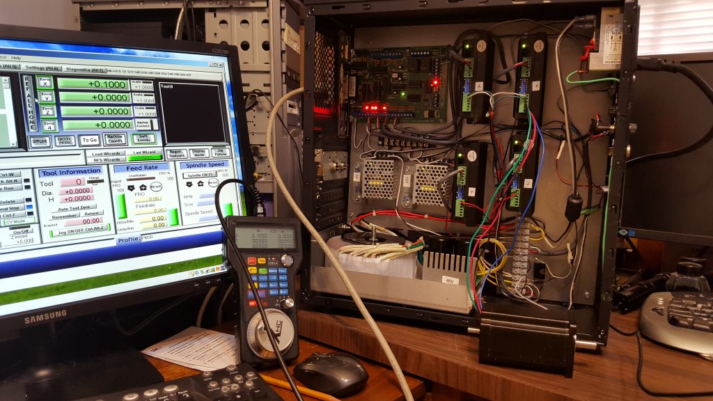
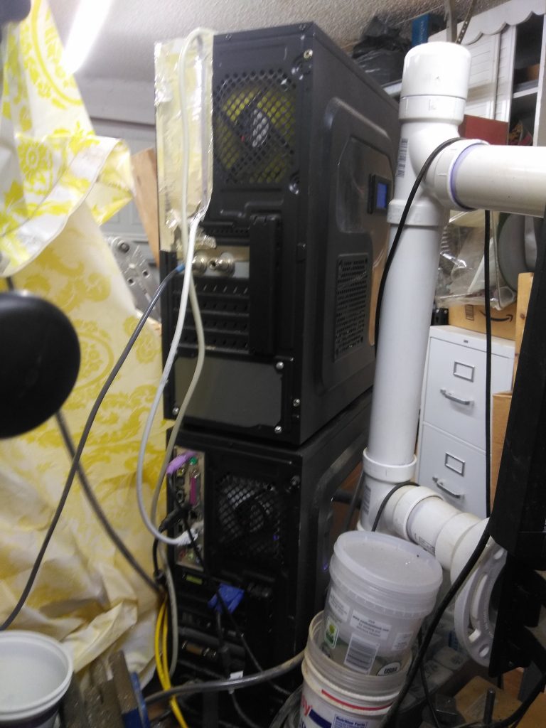
I used my wife’s old desktop computer and installed a small solid state drive in it. I have a license for a Windows XP operating system that I installed on it. I purchased the Mach III Mill program to control the steppers. I disabled all background programs – no firewall no virus checker no internet access, no print drivers, etc. This allows the machine to run fast and not get interrupted by anything. I move stuff on and off the machine using a memory stick or CD. I built a stand for the monitor and keyboard from PVC pipe fittings from Home Depot.

The stepper motor drivers and power supplies:
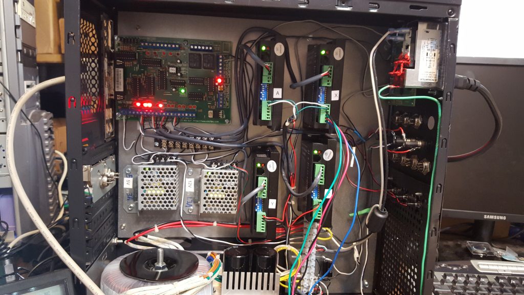
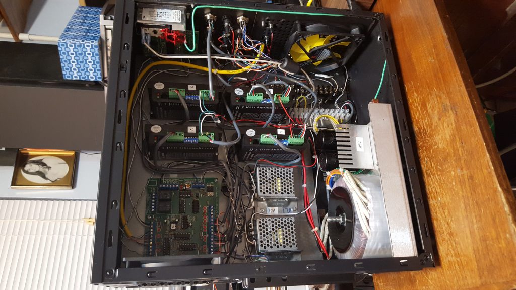
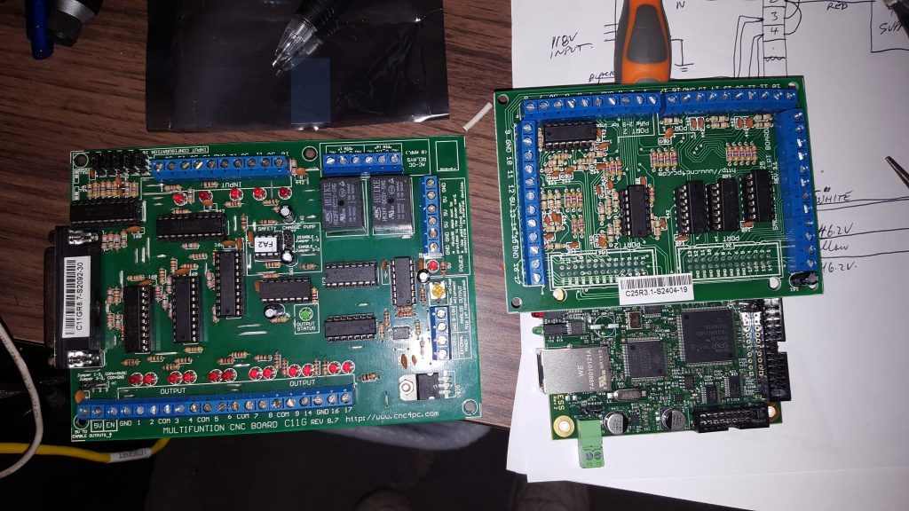
I mounted the stepper motor drivers and power supplies in a computer case. This appeared to be the least expensive and most flexible way to do this. The first controller board that I purchased was a C-11G parallel port interface. It worked for a short while – a trace on the board burned up while I was trouble shooting an issue (my fault). I replaced it with a Ethernet SmoothStepper Motion Control Board (6 axis) which came with a C-25 SmoothStepper terminal board This is a much cleaner solution than the parallel port.
The main suppliers for my parts were Automation Technologies and Allied Electronics (NC contact block, limit switches, pilot lights, etc.)
Here is a list of the major parts I used in the conversion:
| Name | Price | Qty | Total |
|---|---|---|---|
| USB MPG Handwheel for Mach3 Controller, 4 Axis ( X, Y, Z, A) | $98.99 | 1 | $98.99 |
| NEMA23 570oz/in 5A 3/8” Dual Shaft Stepper Motor (KL23H2100-50-4B) | $39.95 | 3 | $119.85 |
| NEMA34 Stepper Motor – 1200oz/in 6amp Dual Shaft (KL34H2120-60-4B) | $99.99 | 1 | $99.99 |
| KL-5056D Digital Bipolar Stepper Motor Driver-32 bit DSP Based | $79.95 | 3 | $239.85 |
| KL-8070D Digital Bipolar Stepper Motor Driver-32 bit DSP Based | $99.95 | 1 | $99.95 |
| Unregulated Linear 625W/48VDC/13A Toroidal PSU (KL-4813) | $139.00 | 1 | $139.00 |
| Mach3 CNC Controller Software | $149.00 | 1 | $149.00 |
| Mach3: Addons for Mill | $50.00 | 1 | $50.00 |
| YW-E01 NC contact block (Allied) | $8.75 | 1 | $8.75 |
| 59985K3 1/2″ dia. shaft coupling – set screw | $15.27 | 2 | $30.54 |
| 59985K3 3/8″ dia. shaft coupling – set screw | $15.27 | 6 | $91.62 |
| 59985K63 acetal disks | $5.24 | 4 | $20.96 |
| A 6B 3-095037 Timing Belt (sdp/si.com) | $9.56 | 1 | $9.56 |
| A 6A 3-32DF03712 Pul. 32 teeth (sdp/si.com) | $18.82 | 1 | $18.82 |
| A 6A 3-16DF03712 Pul. 16 teeth (sdp/si.com) | $12.46 | 1 | $12.46 |

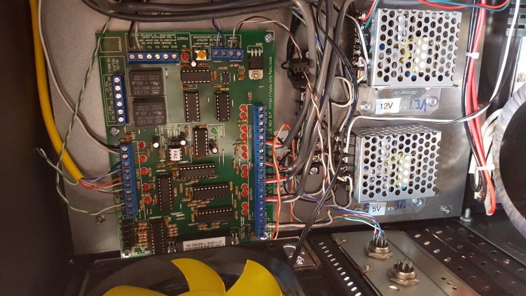
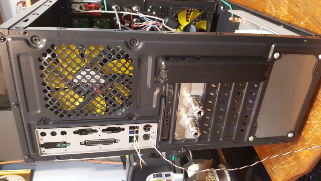
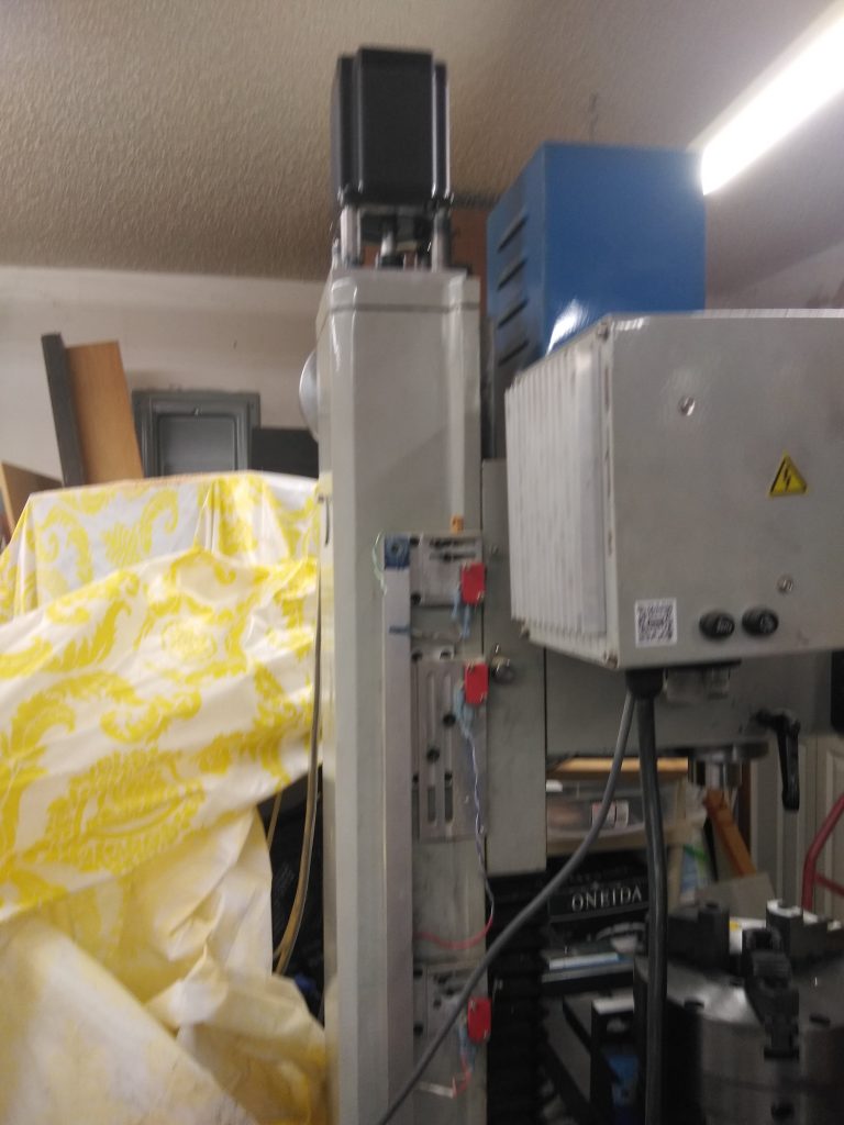
The 48V power supply is on the bottom left. Above it are the 12V and 5V power supplies. Above them is the original G11 board. The drivers are to the right. Hand Controller is in front – works great. Closeup view.
New Controller along side old controller Oops… (cost $!00.00) Z Axis motor mounting plate Hand Controller (really like this) New all in one meter motor on rotary table X axis motor Y axis motor Z axis motor
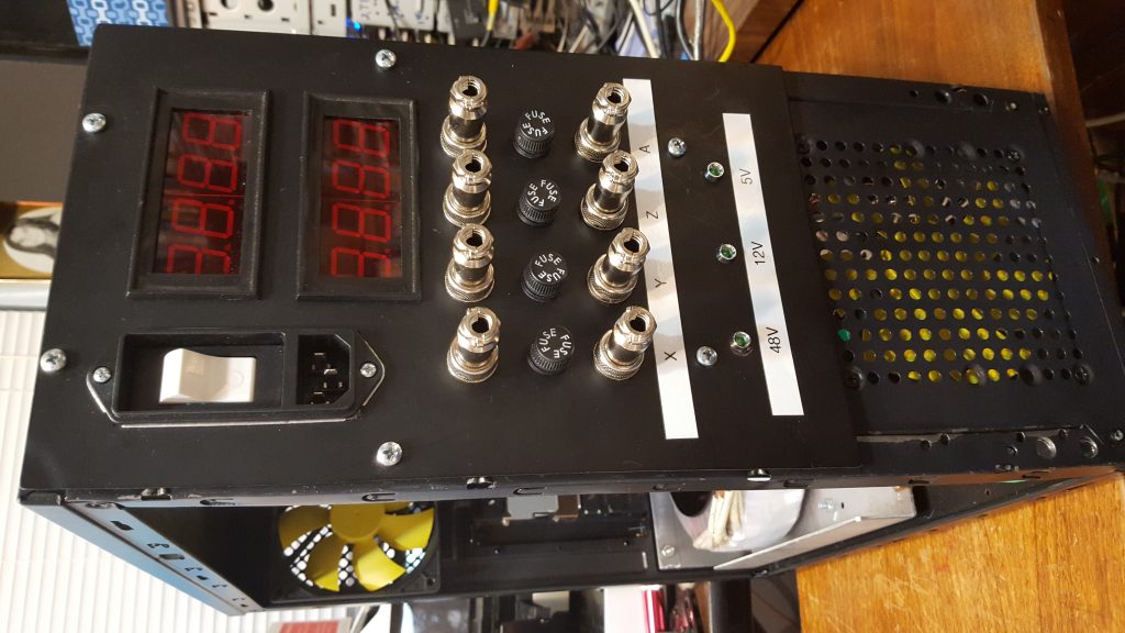
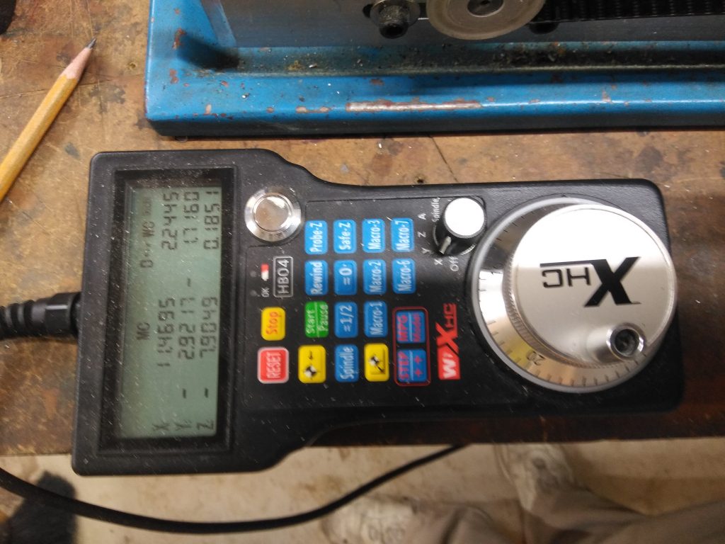
The handheld controller:
This turned out to be a great item. It has a rotary switch to select the axis to control. The large spinner knob moves the axis in either direction as long as you are moving the knob. By pressing the shift button on the keyboard the speed is increased to rapid movement. There are buttons to control the resolution of the movement 1X = .0001 10x = .001 etc. 0X is the normal slow positioning speed. Much easier than the original hand wheels.
C25R terminal map:
This is how I mapped the terminals on the C25R board:
Port 1 (outputs):
| Terminal Number | Axis | Function |
| 2,3 | X | Motor |
| 4,5 | Y | Motor |
| 6,7 | Z | Motor |
| 8,9 | A | Motor |
| all others | no connect |
Port 2 (inputs):
| Terminal Number | Axis | Function |
| 2 | X | Left |
| 3 | X | Right |
| 4 | X | Home |
| 5 | Y | Left |
| 6 | Y | Right |
| 7 | Y | Home |
| 8 | Z | Left |
| 9 | Z | Right |
| 10 | Z | Home |
| 11 | Em Stop Swtich | |
| 12 | Guard Open Switch | |
| 13 | no connect | |
| 14 | no connect | |
| 15 | no connect |
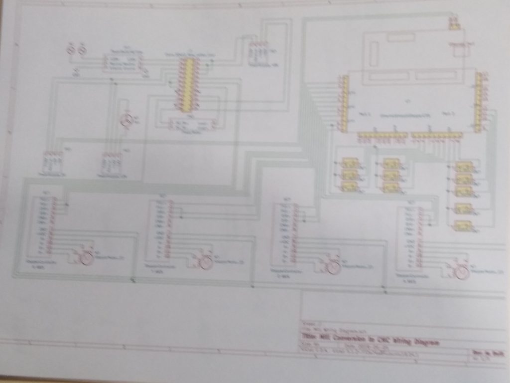
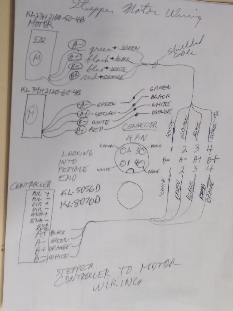
Wiring it up:
Wiring Schematic Sketch to keep track of wire colors
KL8056D Controller dip switch settings:
| 1 | 2 | 3 | 4 | 5 | 6 | 7 | 8 |
| off | on | on | off | on | on | on | on |
| 4.9A | 50% | 1000 | steps/rev |
KL8070D Controller dip switch settings:
| 1 | 2 | 3 | 4 | 5 | 6 | 7 | 8 |
| off | on | on | off | off | on | on | off |
| 6.1A | 50% | 2000 | steps/rev |
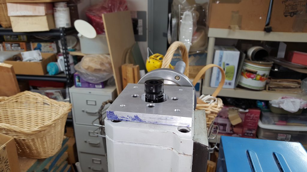
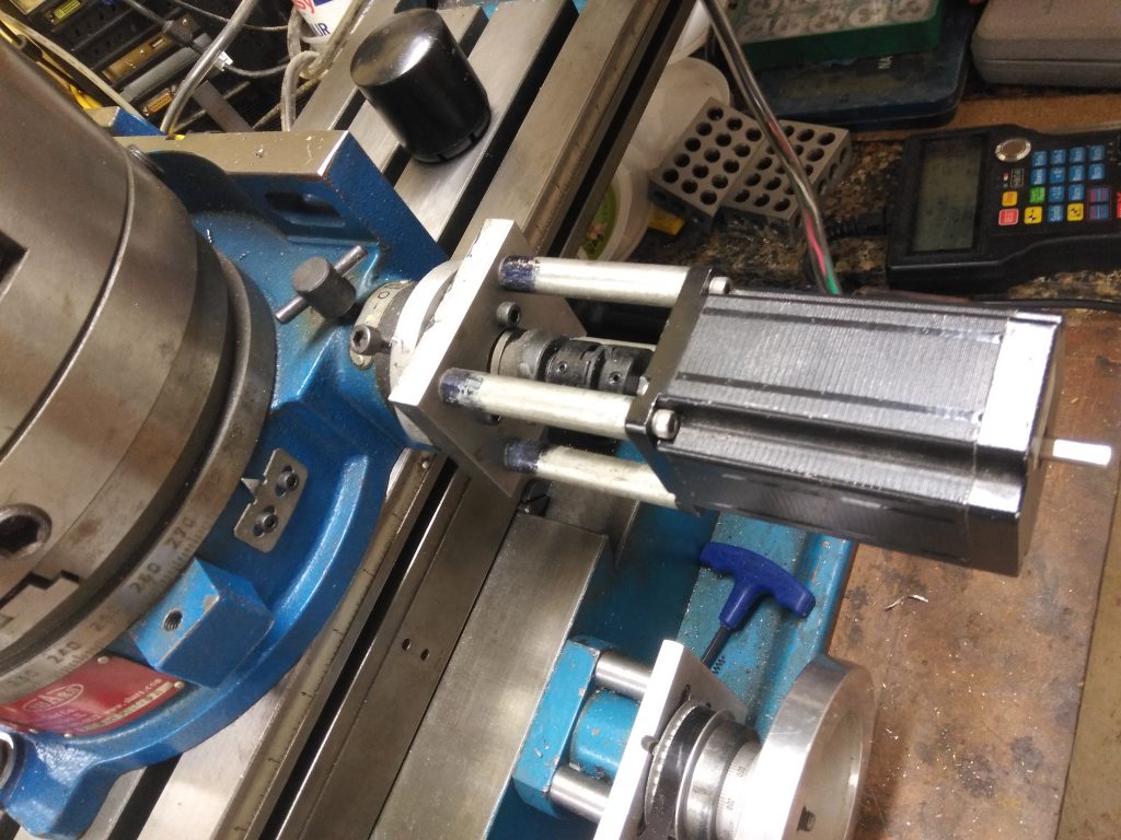
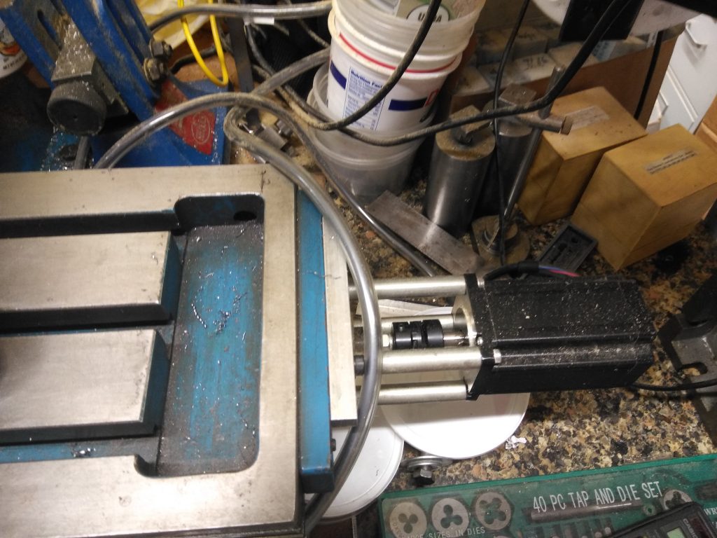
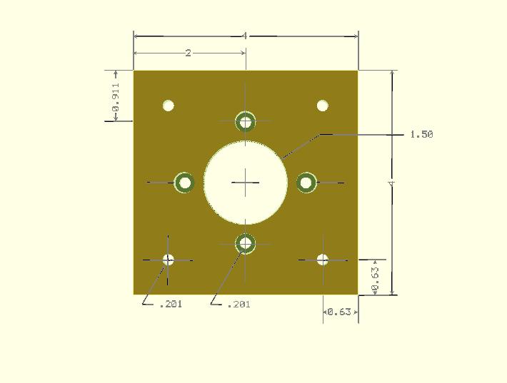
A Axis Details:
The A axis is the rotary table. Just needed to remove the handle and add the mounting plate shown below. I don’t have a sketch for this one. The small pieces that came with the table to allow it to be centered in a mill slot were the wrong size. Had to make my own. It was worth it to do that as I can now change from bottom mount to side mount without losing registration on the Y axis.

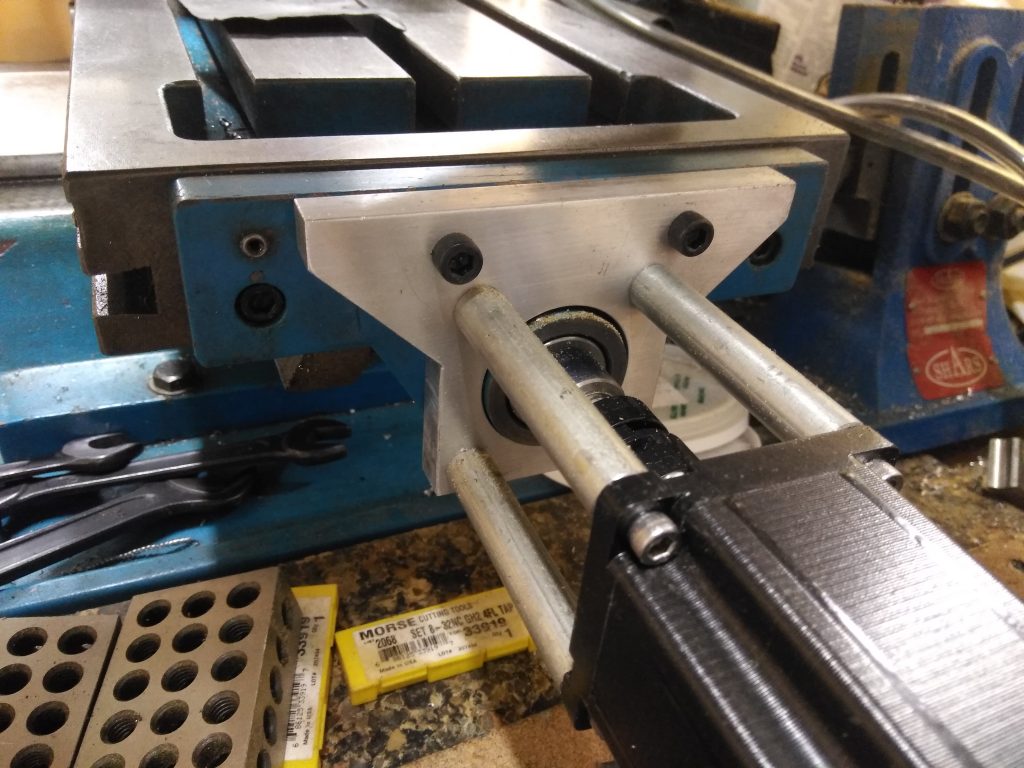
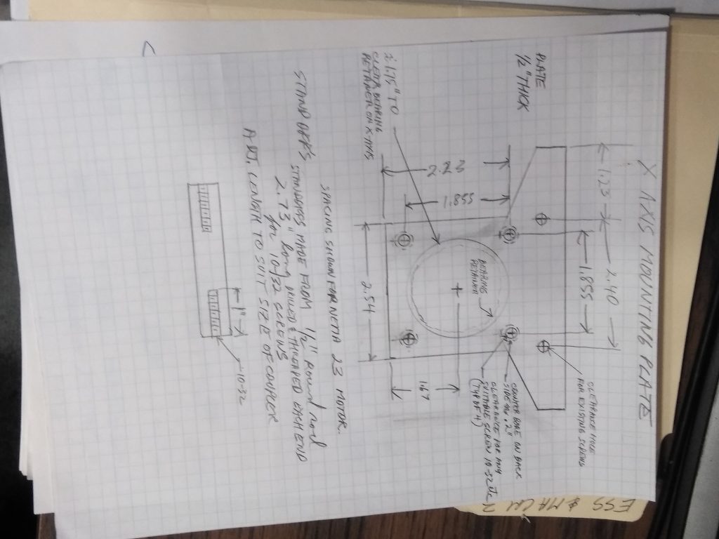
X Axis Details:
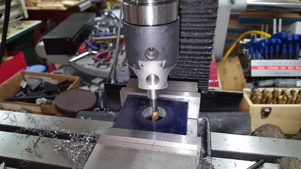
I wanted to keep things as simple as possible. I did not want to replace the bearing carriers with a new custom plate. This appeared more complicated than necessary. I designed a plate that would fit over the existing bearing housing that only required drilling some holes and counter-boring the 4 standoff holes. I mounted the plate using the existing holes in the casting needing only to replace the screws with longer ones. Here is a sketch and picture of the plate:
X axis mounting plate
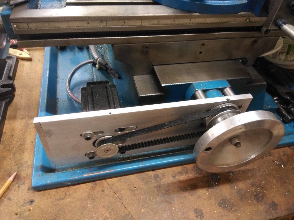
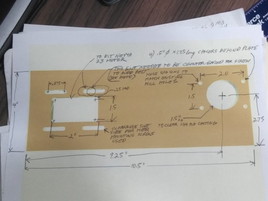
Y Axis Details:
The Y axis was the most difficult to figure out. I did not want the motor sticking straight out of the table. This plate allowed it to be tucked under the table out of the way. The 1.5″ hole clears the 1.44″ bearing housing casting on the mill and the screw holes match the existing casting. No new holes needed to be drilled or tapped. One strange thing: on my mill one of the holes was drilled and tapped at a slight angle – this made no difference when just the bearing housing was being screwed down – but extending the screw out through a 1.5″ spacer and a 3/8″ plate and the hole needs to be spot on – I could not start the screw into the angled hole. Ended up just leaving the screw out. 3 screws out of the 4 are more than sufficient. Also the top left motor mount screw ended up needing to be counter-bored to provide enough clearance for the belt (see picture above). I ran into an assembly issue the large gear on the Y axis. The setscrew wound up being inside the thickness of the plate. My solution was to drill a hole through the top of the plate to allow the set screw to be tightened.
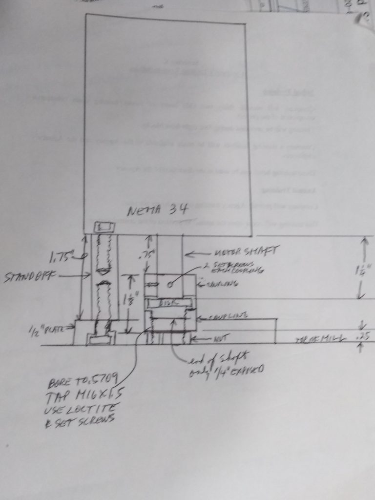
Z Axis Details:
I have plenty of clearance above the mill so there was no reason to not do a direct drive coupling the the Z axis shaft. The Z axis has a motor mounting plate that gets screwed to the top of the column using the existing holes that held down the cap. The standoffs can be any material and just long enough to allow for the coupling to be installed. One side of the coupling is drilled and threaded to match the top of the Z axis screw. The plate is counter-bored .375 X .25 deep. Counter-bore the motor mounts from one side and the cap holes from the other side.
2,000 steps/rev .168″ /rev 2000steps/.168 = 11,904.7619 steps/inch
Example: engraving the pillar tool table:
This is my most ambitious and elegant G-code program to date. I employed the use of subroutines. Rename the file to a .tap for loading into Mach 3. Mounted a Dremmel tool in the spindle of the lathe (unplug lathe for this). The Dremmel allows the bit to spin over 6,000 rpm (hearing protection recommended). The Z axis is fixed at the engraving depth. The program engraves a line and then rotates the A axis one degree to engrave the next line. Note the slow feed rate. The code is well commented.
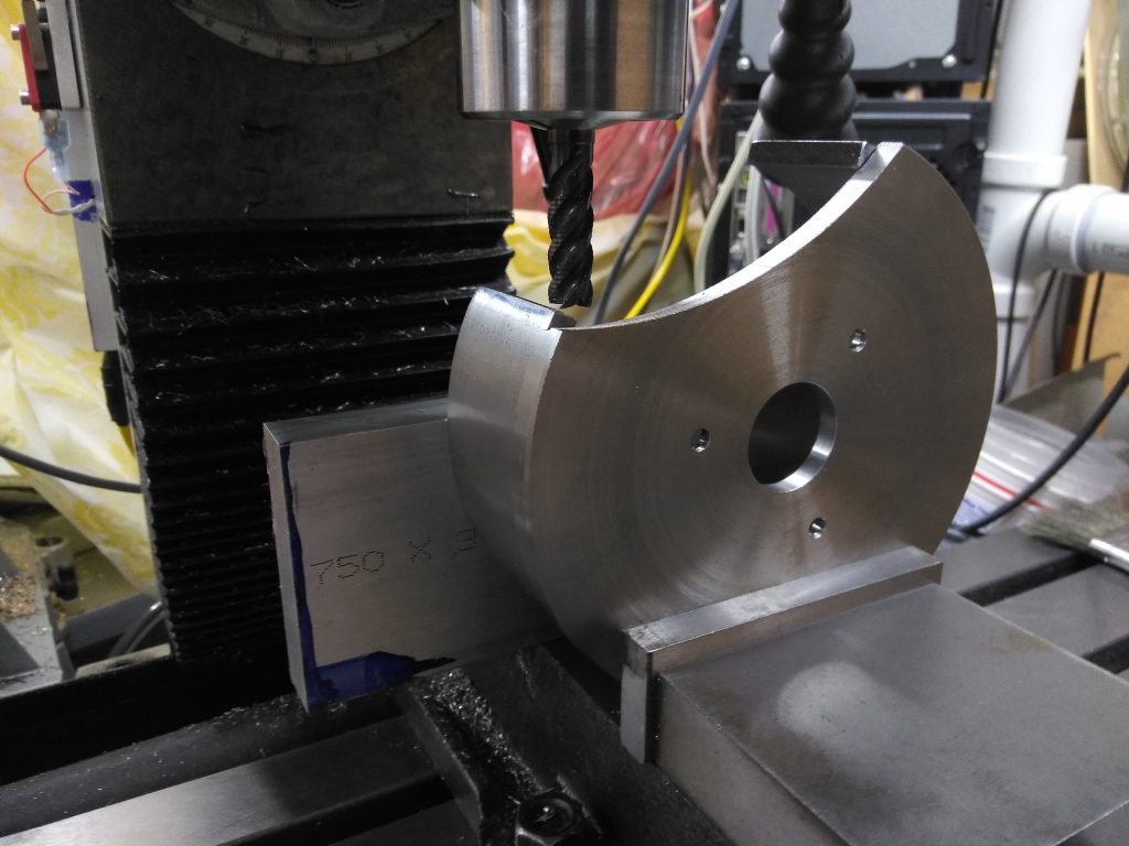
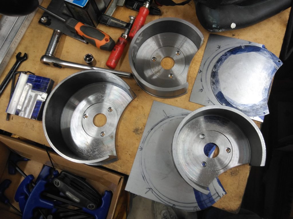
Example: cutting an arc for a grinding wheel guard:
The above files are text file type – the .tap file type was not permitted by WordPress – just rename the file to .tap for use with Mach 3 mill. The first file is to cut out my 7″ guard and the second one cuts out the 6″ guard.
what is difference 3 psu 1 per driver +1 for 24/12v
vs one psu for all ?
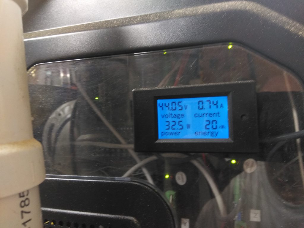
The 48V power supply is just a brute force linear power supply that provides the voltage to the motors. My criteria was enough amperage to drive motors simultaneously – voltage regulation is not important. I’m not sure if three separate supplies could be used. Multiple power supplies could potentially introduce problems – would you common 1 leg of each supply? etc. Do some research first. The 5V supply is needed to feed the smoothstepper controller board and needs to have accurate and stable voltage output and should be a switching style supply. The 12V power supply feeds the cooling fans in the case and can be a switching style or linear style of power supply. The 12v and 5v could come from the same supply if you can find a dual output power supply. I found the individual supplies to be less expensive. See the wiring diagram on this page for details.
We’re you worried about backlash using the stock lead screws?
Mach3 software has backlash compensation which appears to work quite well. You move an axis in one direction to a known point on say a 123 block then see how far you have to move to get to the other side of the block. You enter the difference between the actual length of the block and the move required into Mach 3. Slots come out precisely on spec. If you are milling an arc it will do a very rapid jog to take up the backlash at the reversal point then continue (sounds loud because of the quick change of direction) The arc looks and feels smooth.